


1.完整项目描述和程序获取
>面包多安全交易平台:
quartusii:https://mbd.pub/o/bread/ZZubmJZr
>如果链接失效,可以直接打开本站店铺搜索相关店铺:
>如果链接失效,程序调试报错或者项目合作也可以加微信或者QQ联系。
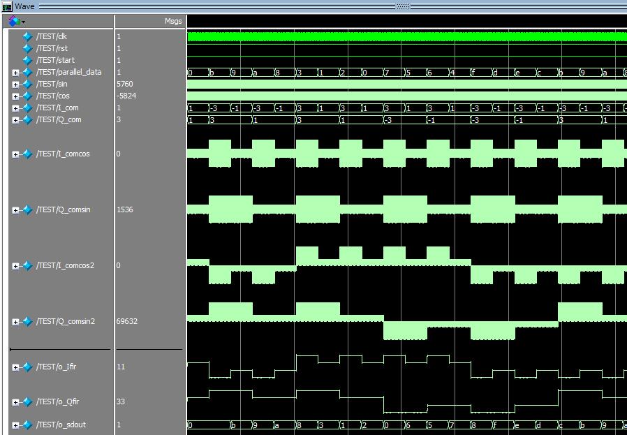
2.部分仿真图预览
3.算法概述
数字信号是通过FPGA的输出端口生成的。在16QAM调制中,每个符号包含4个比特,因此需要一个4位二进制计数器来生成数字信号。计数器的输出被映射到星座图上的一个点,然后通过数字到模拟转换器(DAC)转换为模拟信号。串/并变换器将速率为Rb的二进制码元序列分为两路,速率为Rb/2.2-4电平变换为Rb/2 的二进制码元序列变成速率为RS=Rb/log216 的 4 个电平信号,4 电平信号与正交载波相乘,完成正交调制,两路信号叠加后产生 16QAM信号.在两路速率为Rb/2 的二进制码元序列中,经 2-4 电平变换器输出为 4 电平信号,即M=16.经 4 电平正交幅度调制和叠加后,输出 16 个信号状态,即 16QAM.
4.部分源码
`timescale 1ns / 1ns
module TEST;
reg clk;
reg rst;
reg start;
wire [3:0] parallel_data;
wire [15:0]sin;
wire [15:0]cos;
wire signed[19:0] I_com;
wire signed[19:0] Q_com;
wire signed[15:0]I_comcos;
wire signed[15:0]Q_comsin;
// DUT
tops_16QAM_mod top(
.clk(clk),
.rst(rst),
.start(start),
.parallel_data(parallel_data),
.sin(sin),
.cos(cos),
.I_com(I_com),
.Q_com(Q_com),
.I_comcos(I_comcos),
.Q_comsin(Q_comsin)
);
wire signed[23:0]I_comcos2;
wire signed[23:0]Q_comsin2;
wire signed[7:0]o_Ifir;
wire signed[7:0]o_Qfir;
wire signed[3:0]o_sdout;
tops_16QAM_demod top2(
.clk(clk),
.rst(rst),
.start(start),
.I_comcos(I_comcos),
.Q_comsin(Q_comsin),
.I_comcos2(I_comcos2),
.Q_comsin2(Q_comsin2),
.o_Ifir(o_Ifir),
.o_Qfir(o_Qfir),
.o_sdout(o_sdout)
);
initial begin
clk = 0;
rst = 0;
start = 1;
#10;
rst = 1;
end
always #5
clk <= ~clk;
endmodule
.............................................................................
wire signed[9:0]mcos;
wire signed[9:0]msin;
NCO_Trans NCO_Trans_u(
.i_clk (clk),
.i_rst (~rst),
.i_K (10'd256),
.o_cos (mcos),
.o_sin (msin)
);
assign cos={mcos,6'd0};
assign sin={msin,6'd0};
always @(posedge clk or negedge rst)
begin
if(~rst)
begin
I_comcos2<={24{1'b0}};
Q_comsin2<={24{1'b0}};
end
else begin
I_comcos2<=$signed(I_comcos[14:3])*$signed(cos[15:4]);
Q_comsin2<=$signed(Q_comsin[14:3])*$signed(sin[15:4]);
end
end
//RRC
wire signed[31:0]w_Ifir;
wire signed[31:0]w_Qfir;
fiterRRC uut1(
.i_clk (clk),
.i_rst (~rst),
.i_din (I_comcos2[23:8]),
.o_dout (w_Ifir)
);
fiterRRC uut2(
.i_clk (clk),
.i_rst (~rst),
.i_din (Q_comsin2[23:8]),
.o_dout (w_Qfir)
);
assign o_Ifir = w_Ifir[19:12];
assign o_Qfir = w_Qfir[19:12];
reg [15:0] counter;
reg flag_reg;
always @(posedge clk) begin
flag_reg = 0;
if(rst == 0) begin
counter <= 0;
end
else if(counter == 8145) counter <= 0;
else begin
if(counter == 8144) begin
counter <= counter + 1;
flag_reg = 1;
end
else
counter <= counter + 1;
end
end
parameter D = 20;
always @(posedge clk or negedge rst)
begin
if(~rst)
begin
o_sdout<={4{1'b0}};
end
else begin
if(flag_reg == 1'b1)
begin
if(o_Ifir > D & o_Ifir<= 2*D & o_Qfir > D & o_Qfir<= 2*D)
o_sdout<=4'b0011;
if(o_Ifir > D & o_Ifir<= 2*D & o_Qfir > 0 & o_Qfir<= D)
o_sdout<=4'b0010;
if(o_Ifir > D & o_Ifir<= 2*D & o_Qfir > -D & o_Qfir<= 0)
o_sdout<=4'b0111;
if(o_Ifir > D & o_Ifir<= 2*D & o_Qfir > -2*D & o_Qfir<=
.............................................................................
00_011m